

Introduction of Technology
Principle of assembly using pallets
Here is an example of actual assembly procedure using a pallet.
We have no definitive standards so that we can address various kinds of parts and products and support the current assembly lines and needs of our customers: We know that there are various assembling methods. We provide assembling methods and jig designs flexibly after our sales staff consults with customers.
| Benefits from using pallets |
|---|
| Not only quick assembing,likeda's products also give you many other venefits. |
| Details |
| Example of impressive labor saving |
|---|
| Introduces some examples of achievements in labor saving and cost reduction efforts. |
| Details |

In this example, six parts are assembled.
Refer to the example of assembly of thermo modules.
Four parts are sandwiched between outers A and B.
These parts have different layouts from each other.
1.Outers A and B are set on each of the jigs.

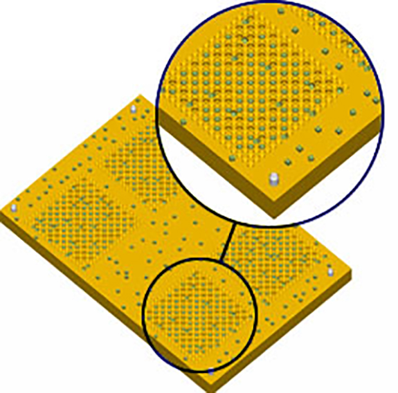
2.Device tables A and B are nested on a pallet.
Devices A and B seem cubical, but their height is slightly greater, so their directions must be aligned.
Since the pallets recognize different parts by the differences in their shapes, it is difficult to align such parts as a matter of fact. We will take appropriate measures, however, based on our long experience and know-how.

[Picture…Pallet for device table B]
※Four parts are placed on one pallet for the demonstration purpose in this example, but actually, it depends on the sizes of customer's products and pallets and the nesting machine model.
Supposing the pallet dimensions are 200 x 250 and the product size is approx. 40, the layout pitch is 4 rows x 45P, 5 rows x 45P, and 20 pieces are taken per pallet. 20 parts can be assembled at a time.

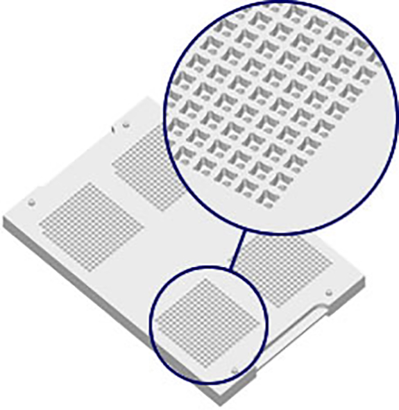
[Picture…Nesting of device table B is completed.]

[Picture…Device table B is assembled into outer B.]
3.The pallet for device table B is sucked from the back and transferred to the jig on which outer B is set.
Better than supply by a part feeder, Ikeda's pallet technique aligns parts on a flat surface at a time and supplies them to the next process, using pallets from the beginning to the end. You never need any special mechanisms for solving troubles due to clogged parts and for handling to make preparations in part supplying to the next process.
Mirroring is applied for pallets for transferring layout shapes.
The optimum pallet configuration depends on the parts to be aligned, the assembly process, and the final posture of the parts desired by the customer.
Meeting your needs flexibly, Ikeda's machines can smoothly be introduced in your production process.
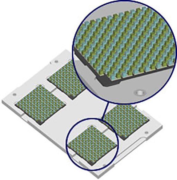
[Picture…Image of nesting of devices A and B]
4.Devices A and B are nested.

[Picture…Nesting of device B is completed.]
In processes 2 and 4, two type of parts can be nested at the same time to different layouts by setting the pallet configuration of the nesting machine to two rows and the tact can be improved on the nesting machine side.
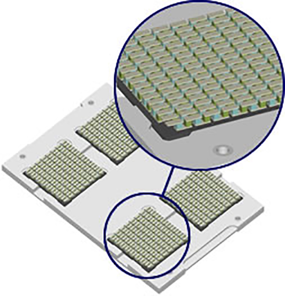
[Picture…Pallet on which devices A and B are collectively nested]
5.Devices A and B are supplied to one pallet and positioned with a guide pallet.

[Picture…A guide pallet for device B is placed.]
Using a guide pallet, you can visually inspect the parts while machine vibration rotates them.
The parts are not scattered or enter other places.


[Picture…Parts are turned by vibration after supplied.]
6.Device B in process 4 is sucked from behind and dropped onto the guide pallet.
Please perform visual check from the top of the pallet during positioning by vibration.
(The figure shows a perspective drawing of the guide pallet.)

[Picture…Positioning is completed.]
With the VI-02-Vac, an integral vacuum-and-vibration type work table, is used, the work efficiency improves greatly.

[Picture…Pallet on which devices A and B are collectively nested]
7.The guide pallet in process 5 is replaced with the pallet for device A, for which positioning is then performed in the same way as in process 6.
Positioning of devices A and B is completed.
[Picture…State after transfer is completed(The devices A and B with parts laid out and aligned in the previous process are placed on outer B and device table B.)]
8.The completed pallet in the previous process is sucked from behind and transferred to the jig on which device table B was assembled in process 3.
[Picture…The parts never fall since cream solder, etc. was applied after the pre-process.]
9.Device table A with parts aligned in process 2 is vacuumed from the back of the pallet transferred to the outer A jig in process 1.

[Picture…The above figure shows the outer A jig is vacuumed and transferred.]
10.The jig, on which outer A is placed, is vacuumed from behind and transferred to the jig in process 1.

[Picture…Assembly and wiring of six parts is completed.]
11.The jig containing outer A is removed and wiring is performed.
※Because the finished parts are aligned, wiring can be made more efficient in the customer's process.

12.Parts are taken out of the outer jig to complete the production process.
Thanks to use of the pallets, parts are efficiently supplied and assembled in series and as a result, they can be transferred easily to the customer's process.
